LilyPad Arduino and light sensors
I found the LilyPad Arduino products while challenging myself to hand-make something for my sister as a gift. The LilyPad is designed especially for textile electronics. In time had made a purse with a blinking LED heart. My sister was thrilled with the final product, and I had stepped outside my developer comfort zone.
Aside from sewing the thing there was plenty of learning to do. As someone who learned to program on the web, many of the benefits of a high-level language like PHP or JS quickly became apparent. But after a couple evenings debugging and learning, I'd brought the LEDs to life in a fun way by getting them to blink in two halves.
The complexity is limited by physical constraints: the wires all have to be sewn into a single flat surface, and none of them could cross in the final design. So although my original plan involved more complexity, I had to stop short and settle with blinking on and off.
Blinking vs fading LEDs
To get past simple blinking, I learned about Pulse Width Modulation. PWM allows a digital display to trick our eyes into seeing non-digital values. Technically an LED only has two settings: ON and OFF. But much like frame-based animation, our eyes can be fooled into seeing various brightness levels by flashing an LED on and off in rapid succession.
This is such a common need that there is a function built into the Arduino API. It's called analogWrite and it allows you to treat an LED as if it had a fader knob controlling it. It accepts an 8-bit number, so any value from 0-255 inclusive.
Example: if you want 60% brightness, analogWrite will instruct the LED to turn itself on 60% of the time and turn off the remaining 40%. This is done at a cycle of approximately 500Hz on most Arduino boards, which is much faster than the optimal refresh rate of 60Hz normally sought after in computing, meaning even low brightness levels can be achieved without too much flicker.
// On many Arduino boards, pin 13 is the on-board LED
int led = 13;

// 255 is max brightness. We want 60% of 255.
int brightness = 255 * 0.6;

// Run once at the beginning
void setup() {
  // Setup the LED as our output.
  pinMode(led, OUTPUT);
}

// Runs continuously without stopping after setup.
void loop() {
  analogWrite(led, brightness)
}
You might be surprised to find out that the above code block is a complete Arduino program! I was at least. Although it cannot respond to any change, it is using all of the same conventions as a bigger, more complex Arduino program. And no wiring was required because it only uses the on-board LED that is soldered to the LilyPad.
This simple program is a great starting point for experimentation with PWM. By using if statements, for loops, and other programming mechanisms, we can fade LEDs or have them respond to user input.
Light sensors
After I finished my sister's gift, a few spare parts were left over and I put them in a box in storage while I went backpacking. Recently while cleaning I found the box of unused components and rediscovered the light sensor.
As I dove into the sensor's workings I was surprised to find how much complexity can be hidden behind a seemingly simple circuit. But its ability to provide variable input is the perfect complement to the PWM-enabled LED we just coded.
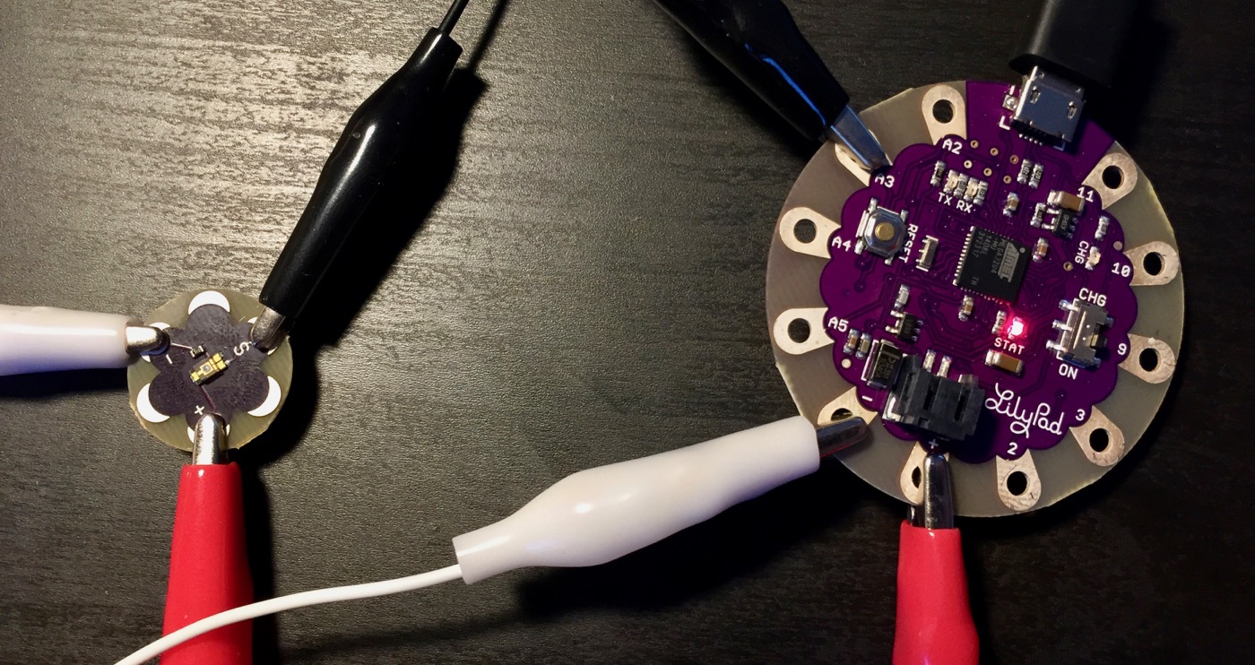
But first, we have to connect the sensor to the Arduino with wires. I've made the following three connections:
- The light sensor's output (labeled with
Son the smaller chip in the left of the photo) is attached to pinA3on the LilyPad main board. - The
+and-power terminals are used to power the sensor. Connect both+terminals with one wire, then both-terminals with another. - The LilyPad's on-board LED is the output, internally referred to as pin
13. It requires no extra wiring since it is on the Arduino.
The sensor outputs a signal as a 10-bit number, which is 210 or 1024 in the familiar base-10 system we use day-to-day. So the sensor output has a range of 0-1023 inclusive, with 0 meaning no light is detected, and 1023 meaning it detects a bright light similar to a clear, sunny afternoon.
If we want to use the 10-bit light sensor with an 8-bit LED output, we need to convert the 10-bit data to an 8-bit number. Not hard! We can divide the higher value by the lower one to find the difference. In this case 1024 divided by 256 equals 4. So as long as we divide our sensor input value by 4, it can be directly sent to analogWrite as an output value.
Below is the code to accompany the specific wiring diagram described above. Look out for the line where the sensor input is read and then divided by 4.
Something else to look for is the delay function, which stops the loop from measuring at the max possible speed and instead pauses for 50 milliseconds between each measurement.
// On many Arduino boards, pin 13 is the on-board LED
int led = 13;

// I chose the A3 analog pin on my LilyPad. Your wiring
// decisions determine what pin you need to listen on.
int sensor = A3;

// initialize brightness but do not assign a value
int brightness;

// Run once at the beginning
void setup() {
  // Setup the LED as our output.
  pinMode(led, OUTPUT);

  // Setup an analog pin to accept sensor input data.
  pinMode(sensor, INPUT);
}

// Runs continuously without stopping after setup.
void loop() {
  brightness = analogRead(sensor) / 4;
  analogWrite(led, brightness)
  delay(50);
}
Now we have our LED responding to the light sensor input! But can we make this even better? Perhaps use input smoothing to stabilize the signal?
Hopefully documenting my steps as an Arduino beginner will be useful to anyone else getting started. If you found anything confusing or would like me to expand a section let me know in the comments!